The goal of this article is to help XMD-S users take advantage of the new technology for designing molds in 3D. As explained in our last article, you can still design the way you’re used to (from section), but today we focus on using XMD commands in 3D design work. Next time we’ll examine how to use KeyCreator commands with XMD-S designs.
Getting to 3D
To get started, you must first switch XMD-S to the 3D drawing. You do this by clicking on the 3D View command or the View Plates Command. Warning: Feel free to use KeyCreator level tools, but they do NOT activate XMD-S 3D mode. Use one of the above commands first, then go nuts with 3D and the level manager.
![]() 3D View: This icon automatically changes to View 7. All 3D levels under Core Half and Cavity half are displayed. 100.6 is set as active level.
3D View: This icon automatically changes to View 7. All 3D levels under Core Half and Cavity half are displayed. 100.6 is set as active level.
![]() View Plates: The View plates command (formerly View Holes), has been upgraded from previous versions.
View Plates: The View plates command (formerly View Holes), has been upgraded from previous versions.
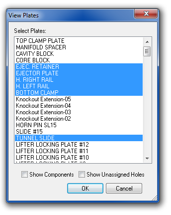
Click View Plates. When the dialog appears, select any number of plates to display. Hold the “Ctrl” key down or click and drag to select multiple plates to display.
You may check the Show Components box to display the 3D components that are assigned to the chosen plate(s).
Click OK to view the selected plate(s).
If you want more or less plates displayed, choose the command again. XMD will remember the plate(s) that were selected the last time, and you can add or remove from the selection.
What you See
Solid Plates
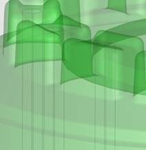
All plates in XMD are now rendered as solid blocks.
Transparency is now used to better see the internal features of the mold. To alter the display, you can use the KeyCreator’s Face Tools (Advanced Modeling, Tools, Face Tools) to change Color, Transparency, or Material rendering of various faces.
Colored wireframe of the holes is drawn as in previous versions of XMD, but better. In XMD-S, Holes automatically and intelligently match the full 3D geometry of all the plates, mechanisms, part data and parting surfaces. This means that holes will begin and end at sensible locations, and will be properly divided amongst the various plates.
Master and Finished Plates
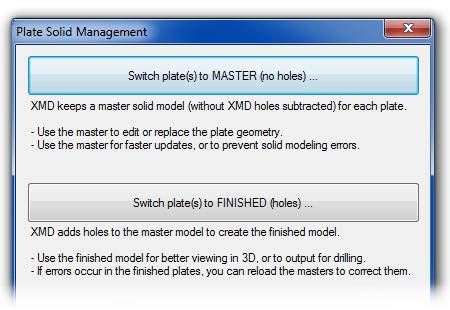
The introduction of solid plates in XMD-S comes with a very important concept for you to understand. Every plate is now represented in either master or finished model.
Master Model: XMD now manages a master model which is the custom component without solid holes subtracted, and may be freely edited with KeyCreator solid modeling tools. Some of the advantages of working on the master model are:
- faster updates
- prevention of solid modeling errors
- they are kept up to date, which comes in handy if you need to revert a recent change

Finished Model: At any time, you can switch to using the finished solid, which takes the master solid and puts holes in it. XMD will attempt to keep the holes up to date but may have trouble on complex, surfaced geometry. Fortunately, if errors occur in the finished model, you can reload the master to correct them. The finished model is useful for:
- better viewing in 3D
- outputting to drilling
- hole faces are opaque so they can be clearly seen.
- Pockets are transparent so you can see what’s in them.
Note: While using the finished model, XMD-S maintains holes automatically. However, XMD-S does not update the solid plates while you are doing work in a 2D drawing. So if instead of switching to a 3D drawing, you just turn on the solid plate level, the plate will not have the new holes put in it yet. Use the 3D Drawing command, and XMD-S will update the drawing.
Switching Models
Configuring the Default Plate Model
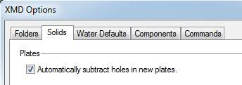
 Using the XMD Config program, you can control whether newly created or converted plates come in as master or finished. The default is for all plates to be in finished mode. To change the setting, load the XMD Config program, navigate to the Hole Configuration page, and check or uncheck the box that says “Automatically subtract holes in new plates”.
Checked – plates come in as finished plates.
Unchecked – plates come in as master plates.
This option can also be changed from within the job. Open the XMD Options dialog (XMD Tools menu), and you will see the same option under the Solids tab.
Level Management
The level structure has been redesigned in XMD-S to make it easier to view the mold in 3D. All plates and components are now divided between level 100 (Cavity Half) or 200 (Core Half). Both the cavity half and core half have a Plates sublevel (100.5 or 200.5) where both moldbase plates and user plates can be found. 3D components can be found under the plate that they belong to. For example, the picture below shows that the locating ring is under the Top Clamp Plate level, which is under the Cavity Half Plates level.
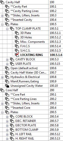
XMD creates three sublevels for every plate:
- 3D Plate – This is where the plate solid is kept.
- 3D Holes – 3D wire hole geometry may be found here (as well as 3D solid waterlines).
- Misc. Components – This level is for users to put custom components they have created on. XMD does not do anything special with this level.
Moving Plates and Components to Different Levels
XMD uses the level structure to associate components to plates. Generally XMD-S will automatically associate standard components and smart patterns according to the start position of the component. If a component is grouped with the wrong plate, or even the wrong mold half, you may want to moved it. You have two ways:
A) Use our Move Components to Plate Levels command. This is the easy way to move components. Until we put it into one of the XMD Menus, it’s located under KeyCreator Add-Ins -> CDE Execute -> XMD Extras -> Move Components to Plate Levels.
Once in the command, all you need to do is pick the plate that you’d like to move the components/plates to, then pick them! That’s it! XMD takes care of moving the entities, creating the proper levels, and cleaning up the old levels.
B) Move levels manually using KeyCreator. XMD-S allows you to freely move any component’s or plate’s level to any other place. You may also move a solid to any other level you choose. XMD-S will remember these levels when changes occur, and will associate levels with plates according to the structure you set up.
Note: Pay special attention when moving plates to move the entire plate parent level. This can be accomplished using KeyCreator View -> Level -> Move Levels.
Designing components in 3D
Add User Plate/Pocket
Adding a user plate in 3D works exactly like it did in 2D. You now have to watch your construction plane to determine which direction the plate will be facing. (XMD-S also fixes a few bugs here.) We suggest you try it, to place an inserted plate into the mold design.
Add User Screw
In 3D you can now place a screw using 2 or 3 faces instead of 2 lines. The first face should be perpendicular to the screw axis. After picking two faces, you need to place the screw. If you set your working depth to your chosen face, you can easily place it from any angle. Otherwise, set your view direction to normal to the plate face, or select existing geometry by which to anchor the screw position. Regardless of approach, XMD-S will automatically calculate the screw size, counterbore, and thread, just as it always has.
Move/Copy Component
Numerous bugs have been worked out of the move/copy family of commands. If you’ve been appalled by their behavior in the past, now’s the time to give them a second chance!
 Add Generic Hole
Generic holes are a little smarter now in XMD-S.
Thru holes will not allow you to specify a length, but will instead look at the solid model and determine it automatically. They cannot span multiple plates, and will adjust their length in response to changes to the plate solid. (If you want to set the depth, use a blind, flat-bottomed hole.)
Blind holes can be created to a specified depth. If the depth spans multiple plates, XMD will split the hole into multiple segments.
Placing Generic Holes
We created a new method of placing holes in 3D:

Face-pt (Face & Point): Select the face that the hole will enter into, and then select a point that is either on, or in line with the face. The hole is placed perpendicular to the chosen face – construction plane and depth are ignored.
Add Smart Patterns
XMD 8.5 started grouping smart patterns in subdirectories, and also added functionality to copy these into the job directory for better management and customizability.
In XMD-S, we also have fixed up the behavior when adding in 3D. Now when you are working in 3D, you can set the construction plane to any direction while adding a smart pattern to orient the component. In addition, once you have the basic orientation, you can use the toggle key to easily choose among six major orientations of the component, followed by rotating the smart pattern around its major axis.
(You will also find these now go on sublevels with a plate rather than a “3D Smart Patterns” level. We’re sure you’ll agree it’s much better this way.)
Water
There’s enough new stuff with water to fill a whole article. Feel free to explore on your own in the meantime.
That’s all for now
Nothing described above is complicated, but some may take time to get accustomed to it. Over time we expect you will come to prefer working in 3D for most of your design work, although there’s also times when 2D is easier and clearer. Stay tuned as next time we’ll start exploring the power of directly editing the mold base in 3D.