For the most part, 2D drawings in XMD-S work the way you’re used to. However, there are some noticeable (and not so noticeable) differences, particularly in the area of plates. This article is designed to shed some light on the changes we’ve made to the 2D plate drawings in XMD-S.
The Solid Factor
The most noticeable difference, obviously, is that plate drawings are now based on the solid model.
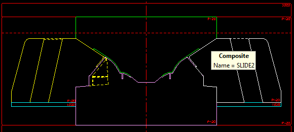
Every feature you design on the plate can be rendered in the drawings you show it in. This new paradigm presented a new opportunity to bring you the highest quality drawings possible.
Automatic Updates, Full Associativity
Automation and associativity is nothing new in XMD, but XMD-S takes this philosophy to a new level. Any change made to a plate solid is automatically reflected in the 2D drawings! Let XMD-S take care of the details while you take care of the design.
Plate Rendering Styles
NOTE: If you’re not familiar with these, you may be wasting a lot of time cleaning up the drawings!
We know you don’t want to spend a whole lot of time cleaning up drawings. That’s why we spent a lot of time building the tools and knowledge to make sure you won’t have to! Many things XMD does for you automatically, like removing chamfers and overlapping lines from the rendering. Other things XMD leaves in your control, so you can decide which details are important to see.
Did you know that XMD-S gives you 4 different rendering modes for every plate in every drawing? These modes are set through the Modify Attributes command. If you ever wished XMD rendered a certain plate just a little bit differently, keep reading!
Section Drawing Rendering Modes
When a plate is shown to a section drawing (or any drawing), XMD-S does it’s best to choose the correct rendering mode. For sections drawings, if the plate solid intersects the cutting plane, the following rendering modes are available to you through the Modify Attributes command:
- Section (default for non-round plates) – Shows only the portion of plate that intersects the cutting plane.
- Section and View (Less Detail) – A view rendering of the plate (showing the full extents) is added to the cross-section rendering. Only visible edges of the plate are shown.
- Section and View (More Detail) – Like the previous mode, except every edge on the plate (both visible and hidden) is rendered.
- View Rendering (default for round plates) – A full detail view rendering. The cross-section portion is not rendered.
It helps to see an example:
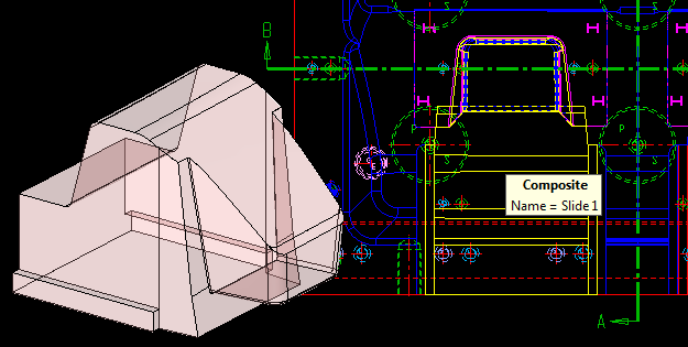
Above is a picture of a slide that’s been converted to an XMD component. As you can see from the core plan, the nose of the slide is intersecting Section B. I went ahead ahead and used the Show to View command to tell XMD to include it in that drawing.
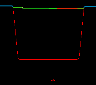
When I switch to Section B, XMD goes ahead and renders the slide (pictured to the left) in Section mode (the default rendering mode). As you can see, XMD did a true section rendering of the slide, which, in this case, isn’t all that interesting!
This is a typical case where you’d want to change the rendering mode to something a little more detailed. We’d much prefer to see the profile of the slide so that when we’re placing components, like water, we’ll know if we’re in danger of hitting the thing.
To do this, we fire up the Modify/Attributes command and change it to Section and View (Less Detail). We could have chosen the “More Detail” version if we wanted to see all the hidden lines, or View mode if we didn’t want to see the solid cross section lines at all.
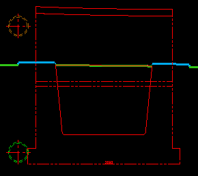
Once we click OK, XMD redraws it in the new mode, pictured to the right. Better move that eye bolt!
(As an aside, we can also see why the material note was so far below the slide in cross section mode. Currently, XMD is putting it at the bottom center of the extents of the plate, not the bottom center of what is actually rendered. Maybe we’ll change this in the future, but it’s easy to move with KeyCreator.)
What if we were to show this slide to Section A where it doesn’t intersect the section? Well the cross-section rendering modes wouldn’t make much sense, so XMD will appropriately default the rendering mode to to either phantom or partly hidden. Some other view rendering options are also available and are discussed in the next section.
Plan Drawing and End View Rendering Modes
Plan drawings and end view drawings are both view renderings, and are done almost identically. The main difference is that the plan drawings include hidden lines by default whereas end views don’t (but of course, this can be changed).
Modify/Attributes gives the following options for both drawing types:
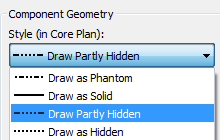
Phantom and hidden are pretty straight-forward, the plate is rendered in isolation and their line font is set accordingly.
Solid and partly hidden are in-place renderings, meaning that the plate may be obscured by other plates. It varies a bit between plan drawings and end views. For end views, solid and partly hidden affect whether or not the hidden lines are rendered.
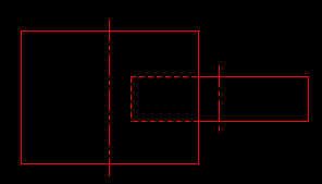
For plan drawings, the only difference between between solid and partly hidden is whether the plate is rendered in place, or in-front of the core/cavity block. This is necessary because XMD supports core and cavity blocks that are not fully surfaced. When a view rendering is done with these big, unsurfaced solids, every plate inside their extents gets rendered as hidden, which isn’t too cool. Rendering certain plates in-front using solid rendering mode is our answer to this problem.
Illustrated below is a common problem that arises with partly-hidden renderings.
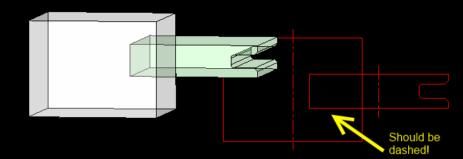
I cut a notch out of the thin plate, and then switched back to my 2D. XMD noticed that I changed the plate and promptly redrew it, showing the notch. Unfortunately, you’ll notice in the picture above that there are 3 solid lines that should have been rendered as hidden lines. Recall that XMD only redraws the plate that has changed, so the obscured geometry is drawn as solid.
To fix the drawing: To get all the proper line fonts, XMD must render all the relevant plates as a unit. Using the Display/Redraw Component command, pick a plate, and have XMD redraw “All Plates“.
Manual Drawing Edits
In the rare event that you aren’t happy with what XMD-S can give you, you can edit a plate’s section manually using Modify/Edit Geometry. As with all components though, beware of doing this too soon. If the 3D plate later changes, XMD will redraw its section and you will lose that edit. Because of this, we recommend you avoid manual edits to the 2D plates until after you have XMD completely redraw of the plates.
Summary
XMD-S automatically generates sections and views for you using sophisticated automatic rendering techniques. You can modify these by showing or hiding plates (and components). Use Modify/Attributes change to the rendering style and color of any mold plate. Drawings will automatically update when the design changes. In views (for efficiency reasons), sometimes you need to manually force a complete redraw to get the hidden lines right. Ultimately, XMD-S will generate everything for you, yet it leaves you in control to decide exactly how your drawings should look.
That’s it for this week, thanks for reading. To learn more about how to design molds better and faster with XMD-S, give us a call.