Archives

XMD-S Is Now Officially 64-bit

Why 64?

The PC world has been 32 bits since the days of the 386 and DOS. This change to 64 bits has been a long time coming. 64 bit software means two things:
1) XMD gets to use 64 bits at a time instead of 32, meaning it’s often twice as fast. (It’s more complex than that, but that’s okay.)
2) You can use all your RAM. Software won’t freak out when it gets to 3GB, which fewer headaches with bigger models such as are common with complex automotive parts these days.

What you need to know


XMD’s licensing system has changed – It’s now entirely software based and will no longer read the hardware dongles.  When you’re ready to make the switch to 64-bit, let us know and we’ll issue you your new licenses.

32-bit XMD a thing of the past – Aside from hardware/operating system requirements, there’s no reason to be using 32-bit XMD/KeyCreator.  For this reason, we will no longer be actively releasing 32-bit versions of XMD.  If this presents a problem for you, please let us know.

KeyCreator requirements – Please make sure you have the latest 64-bit version of KeyCreator installed (2011 V10.5.0) before installing XMD.

Multiple dialog boxes re-designed – This was a requirement based on some technical issues.  Click here for details on what has changed.

What’s New

There’s a lot more goodies packed into this release than just being 64-bit! 
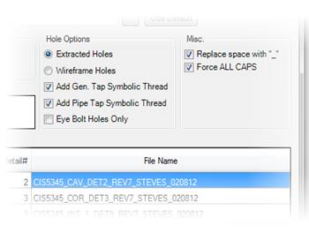
The Export Plate command has been completely redesigned, and now gives users a full range of options, including:

  • Multiple options for generating file names
  • Output directory
  • Output format
  • Type and style of holes

The best part is, most of this stuff can be pre-configured through the XMD Config program so you only have to set it once!

For more info, click here.
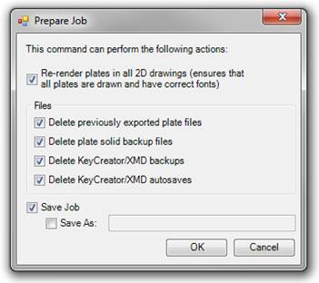
 

There’s a new “Prepare Job” command which can perform a variety of tasks to make your life easier.

This is an ideal command to run when you want to:

  • Increment the job revision
  • Send the file out over FTP
  • Prepare the job to be viewed in Spectrum.
  • Archive the job.
  • Free up disk space.


Fixes/Improvements

  • Plate face/body colors are now maintained throughout the design process.
  • Setup geometry on levels 500.2/500.3 is no longer getting corrupted and crashing KeyCreator when the level is turned on.
  • Interference Checking waterlines against plate faces is now much faster.
  • Smart Pattern browse dialog now remembers the last directory you were in and is now resizable.
  • So much more! Click here to see the full release notes.


How Can I Get It?

Easy: Just contact us today!

Current customers, give us a ring when you’re ready to upgrade. We’ll send you the download link and walk you through setting up the new licenses.

Everyone else: If you have been waiting for the right time to move forward, the time is now! [XMDS] is light-years ahead of XMD, and can out-compete any other mold design tool for power and speed. Call us and we’ll be glad to prove it, let you see for yourself.
Getting into XMD-S the Easy Way

If you know XMD and are just getting into XMD-S, this article is for you.

XMD-S is XMD made better: solids, 3D models, and a lot more intelligence.  But don’t let all this scare you.  We worked hard to make sure XMD-S still works the way you remember.  In fact, you can totally ignore the solid model, work in sections with your part surfaces, and everything will work exactly the way it did in XMD 8.5.

Well, almost.  There are a few small things you need to know.  This article will explain them to you.

Automated Mold Design
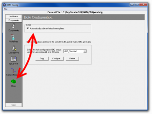
Speed things up by turning automatic hole subtraction off.

Configuration

XMD-S introduces solid plates, and can automatically drill holes in those plates for you.

If you aren’t working in the 3D model, you can turn these holes off in the configuration, and you will get the wireframe holes XMD has always drawn.  (XMD is faster when it doesn’t make these solid holes.)

During design, the new plate management command can be used to turn solid holes on and off.


Startup

The rules for startup are the same.  Here’s the summary:

Where does my part go? Levels 100.1 and 200.1, just like in previous XMD.

Where do my parting line surfaces go? The parting line levels, 100.2 and 200.2, just like in previous XMD.

Can I put the surfaces in my core block? You don’t have to.  XMD automatically knows the core block will be milled to match the part and parting lines.  It will design things accordingly.

A future article will explain putting surfaces into blocks.  For getting started, just follow the above rules and don’t worry about it.


Sections

Section drawings are now generated from solid, but basically work the same as before.  Jogged sections and angled sections are slightly improved (and a few bugs have been fixed as well).  All the XMD commands should work in section as well as they always have.


3D View

XMD-S draws solid plates instead of wire plates, and the levels have changed.  Plates are now divided into core and cavity halves on 100.5 and 200.5, and the components have been grouped with their respective plates.  The View Plates command (previously called View Holes) has a new option to let you see the components and plates together.

There is a lot of power to edit the 3D model directly, but if you are easing into XMD-S you don’t have to worry about that now.  You can do everything the same as before.  Many commands have been enhanced in 3D, so you are welcome to try things.


Plate Details

XMD used to draw plate details based on a 3D wire plate and 2D wire holes.  For XMD-S we switched this to go entirely based on the solid model.  Generally this works well, but of course to do this requires holes be drilled into the solid.  If you configured them off previously, XMD-S will ask you to turn on solid holes now to create the detail.


Smarter Water

Water is perhaps the most changed.  You work in any plate now, not only core block and cavity block.  We also introduced a new smart water command that supports design in any plate.  You may have seen demos working in a solid model, but it works equally well in section and plan drawings.  Yet we kept all the old commands too, so you’re free to use them the way you used to.  Move and copy have changed to dynamically set the length.  Trim has changed to automatically detect which end is open and trim the other side instead.


So If everything is the same, why upgrade?

Download: What's New in XMD-S
Actually, much has changed.  This article just serves to show how easy it is to get started.

Once you’re comfortable with working in XMD-S, you will want to take advantage of the power added by direct solid modeling.  Use KeyCreator to cut a pocket in your manifold plate, and XMD-S will draw its section automatically.  Import a 3D slide and convert it to an XMD component to automatically get holes.  That’s just two new things you can easily do with XMD-S.

For the complete list of improvements, see What’s New in XMD-S [pdf].


Bottom Line

Get your system administrator to install XMD-S 9.0 today (get it here).  Use it on your next job, like you’ve always used XMD. 

Week by week,  pick up new tools and tricks to add speed and power to your design work.  We’ll be your guide.  Stay tuned, in two weeks we start delving into new and faster ways to design with XMD-S.

P.S. – One more reason to upgrade:  Incredible Support.   At Cornerstone, we’re providing faster and higher quality service than ever.  If you ever run into any difficulties learning or using XMD-S, just email or phone us.  Whether the solution involves examining your job, correcting some data, teaching you new techniques, or even changing the software to meet your needs, we will do what it takes to keep you efficient.   When you call, we will serve.


The XMD-S Users List

If you use XMD-S (Expert Mold Designer), you’ll want to keep informed.

Did you know we have a mailing list just for users of the latest software? We use it to let our customers know when bugs get fixed, features get added, and to teach designers better ways to use our software.

Next week we are beginning a new series of of instructional messages on Getting Started with XMD-S. Learn what’s changed, and what hasn’t, and what you need to know to take full advantage of our tools.

So if you’re using XMD-S, or planning to use it soon, you need to get signed upTo sign up, just email me, alanb@corintsoft.com and I’ll add you to our users list.

Ejector Pin Charts

It’s common in manufacturing custom mold bases that steel mold plates deviate from designed thickness by slight amounts. Which of course means your pins must also be adapted to match. This can involve a lot of error-prone manual calculation. Or… you can just use the automated pin charts that XMD-S generates for you!

The Ejector Pin Chart's secret hiding spot revealed!

Over the past couple of months, we’ve found that a number of XMD users were in the dark when it came to the Ejector Pin Chart feature of XMD. Some didn’t realize its capabilities, whereas other didn’t even know it existed!  Hopefully, this post will shed some light on one of XMD’s best kept secrets, and show that this quick and easy tool can be a huge time saver!

What does it do exactly? It automatically creates a chart of all ejector pins in the job, as well as a chart indicating the actual plate sizes.  The ejector pin chart includes the cut-off lengths, actual lengths, catalog #’s, detail #’s, and more.  Scroll to the bottom to see a picture of the final result.

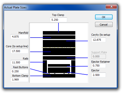
For years, the Ejector Pin chart command has been “hiding” in the XMD Tools menu.  Assuming you have some ejector pins in your job, running the command brings up the Actual Plate Sizes dialog, pictured below.

Enter the actual plate sizes from the shop floor into this dialog

We all know that when it comes to ordering steel, you generally get plates a little bigger than the design calls for.  When you finish up the plate, the actual size is often different from the designed size.  In order for XMD to properly calculate the ejector pin length, you need to tell it how big the plates actually are.  So once you have that info from the shop floor, enter it into the Actual Plate Sizes dialog, and hit OK (XMD will save this information so you won’t have to enter it again).

Next, enter the amount of stock that should be left on each pin, and hit OK.
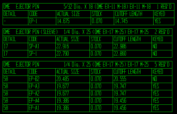
All that XMD needs to know now is where you want to draw the charts, and voila!  A complete ejector pin chart is automatically generated for you, ready to send to the apprentice mold maker (I remember those days!).

The XMD-generated Ejector Pin Chart

Finally, you can place a table that indicates the actual plate sizes that were used in the calculations.

Actual plate sizes